




Process Timers: How to Select, Configure, and Test Them
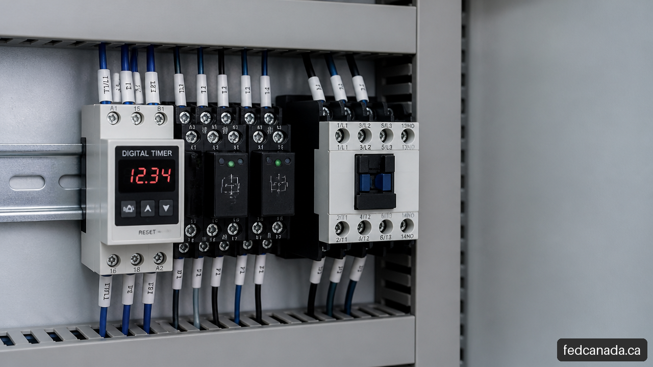
Process Timers control an output after a defined delay, for a defined interval, or on a repeating schedule. I recommend selecting them from the actual process sequence and failure consequence, not simply from the widest advertised time range. A timer that counts accurately but restarts a pump after a power interruption, for example, may still be the wrong control device.
Table of Contents
- Understanding Process Timers
- How to Specify the Right Timer
- Installation, Load Control, and Commissioning
- Key Takeaways
- Frequently Asked Questions
- Sources
Understanding Process Timers
What a process timer does
A process timer is a control device that changes an electrical output based on elapsed time or a calendar schedule. It may energize a relay, open a contact, start a sequence, or provide a signal to another controller. In practical terms, it turns a time based instruction into a repeatable action.
For example, a timer can delay a fan start until a heater has stabilized, keep an exhaust fan running after cooking equipment shuts down, cycle a lubrication system, or operate equipment during planned business hours. Digital timers used in industrial automation and process control commonly support time based event control, including on delay, off delay, interval, and cyclic functions.
The central question is not, “What timer should I buy?” It is, “What should happen when the initiating event occurs, disappears, repeats, or fails?” That sequence determines the timing mode, inputs, outputs, and recovery behavior.
Timing modes and the process behavior they create
Timers are often grouped by mode, but the names alone can be misleading. The following comparison focuses on what each mode does to the process.
| Timer function | Output behavior | Suitable use | Avoid when |
|---|---|---|---|
| On delay | Output activates after an input remains present for the preset time | Staged startup, delayed fan activation, nuisance trip filtering | The process requires an immediate protective response |
| Off delay | Output remains active after the input is removed | Fan run on, purge cycles, cooldown | Power loss could leave the process in an unsafe state |
| Interval | Output activates for one preset duration after a trigger | Timed dispensing, one shot valve actuation, alarms | The action must stop based on sensor feedback instead of time |
| Repeat cycle | Output alternates between on and off periods | Lubrication, dosing, circulation, flashing indicators | Cycle length must change dynamically with process conditions |
| Time switch | Output follows clock or weekly schedule | Signage, lighting, planned operating hours | The event depends on a machine state or product sensor |
An on delay timer starts counting when its control input or supply condition is satisfied. Its output changes only after the set time expires. If a conveyor needs a two second delay before starting after an upstream machine, this can reduce simultaneous inrush and stage the sequence.
An off delay timer does the reverse. When the control signal disappears, the output stays energized for the configured period. Consider a hood fan that needs to clear residual heat or vapour after cooking equipment stops. The fan signal ends, but the timer keeps the fan command active long enough to complete the purge.
An interval timer creates a defined pulse. A trigger can energize a solenoid for five seconds, then release it automatically. A repeat cycle timer alternates between two timed states. This is useful for simple recurring actions, but it does not confirm that the action produced the intended result. A dosing pump may run for ten seconds every hour, yet a blocked line or empty container can still prevent delivery.
A timer controls when an output changes. It does not automatically verify that the physical process responded.
Process timer, hour meter, and PLC timer instruction
These devices are related, but they are not interchangeable.
An hour meter records accumulated running time. It supports maintenance planning and asset use monitoring, but ordinarily does not control an output. Newark describes hour meters as tools for recording total operating time for maintenance planning and equipment monitoring. A compressor may receive service after a specified number of operating hours, but the hour meter does not decide when to start or stop it.
A standalone time relay or process timer performs a focused timing function in hardware. It is often a sensible choice when the logic is independent, transparent, and unlikely to expand.
A PLC timer instruction is software logic inside a programmable controller. It is stronger when timing depends on several sensors, permissives, alarms, interlocks, recipes, or operator commands. The timer instruction can be diagnosed, displayed, logged, and coordinated with the wider sequence.
For scheduled operation, use a time switch rather than an elapsed process timer. The Omron H5L A scheduled timer supports up to 24 programmed on and off steps, scheduling from 24 hours to seven days, and memory protection for programmed settings during a power failure. That retained program is useful, but it should not be assumed to mean the device retains elapsed timing progress during an interruption.
How to Specify the Right Timer
Start with the sequence and failure consequence
I recommend documenting the sequence in plain language before comparing products. Write down the initiating condition, the required delay, the output action, the end condition, and the required response to faults. This forces the specification to reflect the process instead of the catalog description.
A practical specification can follow this sequence:
- Define the trigger: power applied, contact closure, sensor signal, pushbutton, or scheduled time.
- Define the output: relay contact state, transistor signal, control voltage, or communication signal.
- Define what ends the action: elapsed time, input removal, sensor confirmation, operator reset, or PLC command.
- Define power interruption behavior: reset, restart, resume, hold output off, or require manual intervention.
- Define the consequence of an early, late, missing, or stuck output.
Consider a washdown pump that should run for 30 seconds after an operator presses a button. A simple interval timer may work if the pump operation is low consequence and the system has separate overload protection. If dry running could damage equipment or create a sanitation issue, a timer alone is incomplete. Add a level switch, flow confirmation, overload protection, and a defined reset sequence.
For a heater, the consequence is usually greater. A normal process timer should not become the only means of limiting temperature, preventing overheating, or protecting people. Where a function is safety related, use a control architecture specifically designed and validated for that purpose. Ordinary timer contacts, even when reliable in normal control duty, are not automatically safety rated.
Accuracy, resolution, repeatability, and drift are different
A broad time range is not a complete timing specification. Four related properties affect whether a timer is suitable.
| Selection factor | What it means | Why it matters |
|---|---|---|
| Accuracy | How close the measured delay is to the set value | Important when the process has a narrow allowable time window |
| Resolution | The smallest setting increment or displayed step | Determines how finely an operator can set the delay |
| Repeatability | How consistently the timer produces the same delay over repeated cycles | Important for cyclic dosing, repeatable sequencing, and quality control |
| Drift | Change in performance over temperature, age, voltage variation, or time | Important in hot panels, outdoor enclosures, and long running equipment |
A timer may allow a setting of 10.0 seconds yet still be unsuitable for a process that needs extremely tight timing consistency. Resolution tells you how finely you can enter a value. It does not prove the timer will produce that exact result every cycle.
For instance, an oven exhaust sequence may tolerate a few seconds of variation. A short chemical dosing pulse may not. The correct choice depends on the process tolerance, not on whether the front panel has a digital display.
Model documentation should be checked for accuracy, repeatability, supply voltage tolerance, ambient temperature limits, and the timing base used. The Omron H3DK M1 multi range timer illustrates why model specific review matters: timing mode, range, mounting, output arrangement, and environmental specification are all part of selection.
Select the supply, output, and mounting arrangement
Supply voltage must match the available control power, not the power feeding the final load. A 24 volt DC control circuit may use a timer that drives an interposing relay, while the relay or contactor switches a separate 120 or 240 volt load circuit.
Output type matters just as much. A timer may offer relay contacts, solid state outputs, or transistor outputs. Relay contacts are electrically simple, but their contact rating is not a blanket approval for every load. Motors, transformers, solenoids, and some heaters can draw substantial inrush current or create inductive voltage transients when switched off.
The Omron H3CR A8 multifunction timer provides five operating modes, timing ranges from 0.05 seconds to 300 hours, and relay output details. Those features make it useful for evaluating a real sequence, but the final decision still requires checking the exact load and wiring arrangement.
Choose mounting based on the panel and service requirements:
- DIN rail mounting supports compact control cabinet layouts and faster replacement.
- Panel mounting can provide direct operator access to settings and status displays.
- Plug in bases can speed replacement, but terminal security and vibration resistance must still be evaluated.
- Screw terminals are common for permanent panel wiring, provided conductor size and torque requirements are followed.
For Canadian installations, the complete control panel and machine may need to meet applicable electrical, enclosure, and machine safety requirements. The correct compliance path depends on the installation, jurisdiction, equipment type, and whether the panel is built as part of a certified assembly. A product marking alone does not confirm that the completed machine or control panel is compliant.
Installation, Load Control, and Commissioning
Wire the timer as part of a control chain
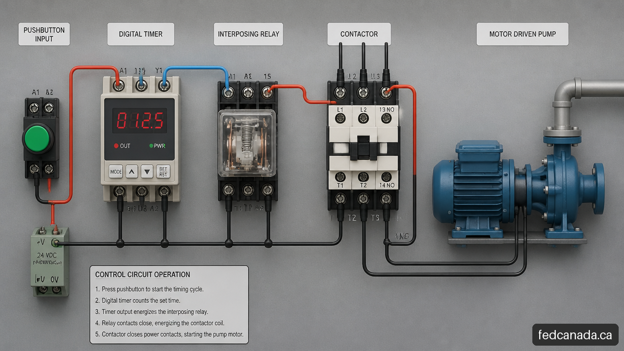
A timer should be viewed as one link in a chain:
- An initiating input detects a command or condition.
- The timer changes internal state and measures time.
- Its output contact or signal changes state.
- An interposing device, if used, switches the load circuit.
- The actuator responds.
- The process produces a measurable result.
Commissioning only the displayed setpoint checks step two. It does not prove the other five steps occurred correctly.
An interposing relay or contactor is often appropriate when the timer output is controlling a motor starter coil, high current heater circuit, pump, solenoid, or voltage level that exceeds the timer output capability. It can provide electrical isolation and make replacement of the final switching device easier. For inductive loads, suitable suppression may be needed to reduce electrical noise and stress on contacts. The appropriate approach depends on AC or DC circuitry and the component manufacturers’ instructions.
The Veeder Root CX202A6 programmable timer supports on delay, off delay, interval, and asymmetrical repeat cycle functions, with delay settings from 199.99 seconds to 199.98 hours and specified ambient operation of approximately 0 to 60 °C. Those details are useful, but they do not establish that its relay contacts can directly switch every pump, heater, or motor load.
Specify power failure behavior before it becomes a fault
Power interruption behavior is one of the most overlooked timer requirements. A timer can respond in several ways:
- Reset elapsed time to zero and wait for a new trigger.
- Restart timing when power returns.
- Resume timing from a retained elapsed value.
- Restore stored programming but not the active timing state.
- Return with the output in a default state that requires manual reset.
The safe choice depends on the process. A refrigeration defrost sequence, for example, may need a carefully controlled restart strategy. A fan purge sequence may need to restart or continue after power restoration, while a chemical feed sequence may need to remain off until an operator verifies conditions.
Do not infer behavior from phrases such as “memory backup” or “settings retained.” Those statements may apply only to programmed parameters. Ask whether the device retains the active timer state, how it behaves if its input remains active during restoration, and whether the output energizes immediately after recovery.
Test the entire timing chain
A good commissioning test measures the real event, not merely the timer display. For a short delay, use a controlled trigger and a measured output response. For longer delays, document start and end timestamps, then repeat the test under expected operating conditions.
A practical test sequence is:
- Verify supply voltage at the timer terminals under load.
- Confirm the initiating signal reaches the correct input.
- Set the required mode and range, then record the setpoint.
- Measure the output transition time over multiple cycles.
- Verify that the interposing relay, contactor, valve, fan, or motor actually responds.
- Test a controlled power interruption where the process permits it.
- Record the expected recovery state and compare it with the observed result.
Troubleshooting should follow the same chain. A timer that starts too early may have the wrong mode, an unstable input, a wiring error, or electrical noise. A timer that resets unexpectedly may be losing supply voltage, receiving a momentary reset signal, or operating outside its environmental limits. Relay chatter can indicate low control voltage, a loose connection, an unsuitable load interface, or a noisy input signal.
When faults are intermittent, measure rather than guess. Check terminal voltage during the failure, inspect the input state, observe the output indicator, and confirm the actuator’s response. This separates timer logic faults from load circuit faults.
Key Takeaways
The practical selection rule
I recommend choosing Process Timers by working backward from the required process result. Identify what must happen, what may fail, and what the equipment must do after a power interruption. Then select the mode, timing characteristics, output interface, and control architecture.
- Use a standalone timer for a simple, independent timing task with clear inputs and a low complexity sequence.
- Use a PLC timer instruction when timing depends on multiple states, sensor feedback, alarms, recipes, diagnostics, or future changes.
- Use a time switch for calendar based operation rather than elapsed process control.
- Use an hour meter to plan maintenance, not to control a process action.
- Use an interposing relay or contactor when the final load exceeds the timer output’s verified switching capability.
- Treat power failure behavior as a written requirement, not an assumption.
- Do not use an ordinary process timer as the only protective device for a safety related function.
The most dependable timer installation is usually not the most feature rich one. It is the one whose behavior is understood at startup, during normal cycling, under load, and after an interruption.
Frequently Asked Questions
What is a process timer?
A process timer is a device or software function that changes an output based on elapsed time or a schedule. It can delay a start, extend a run period, generate a timed pulse, or repeat an on and off cycle.
How does an on delay timer work?
An on delay timer begins counting when it receives its initiating signal. Once the preset delay expires, its output changes state. If the input drops before the delay completes, many configurations reset, but the exact behavior must be verified for the selected model and wiring method.
What is the difference between on delay, off delay, interval, and repeat cycle timing?
On delay waits before activating an output. Off delay keeps an output active after the trigger ends. Interval timing activates an output for a defined duration after a trigger. Repeat cycle timing continuously alternates on and off periods until it is stopped.
How do I choose the correct time range and resolution?
Choose a range that covers the required delay without forcing the setting to the extreme end of the dial or display range. Then check the smallest configurable increment, timing accuracy, repeatability, environmental limits, and the process tolerance for early or late switching.
Should I use a digital timer, analogue timer, PLC timer, or time relay?
Use a simple analogue or digital time relay for independent tasks with stable requirements. Choose a digital unit when clear configuration and status visibility are useful. Use a PLC timer when timing must interact with several inputs, alarms, interlocks, or process logic. Use a time switch when clock based scheduling is the real need.
How does a process timer behave after a power failure?
It depends on the model and configuration. Some timers reset, some restart, some retain programmed settings, and some may have other restart behavior. Verify both retained settings and retained elapsed time separately, then test the completed circuit under a controlled interruption.
Can a process timer switch a motor, solenoid, heater, or pump directly?
Only when the timer’s output type and rated switching capability are verified for that exact load and duty. Inductive loads and high inrush loads can require a relay, contactor, overload protection, or suppression components. A relay contact rating alone is not enough to assume direct switching is appropriate.
Can a timer be used in a safety related machine function?
Not unless the complete device and control architecture are specifically designed, rated, and validated for that safety function. Standard process timers are useful for normal operating sequences, but they should not replace emergency stopping, guarding, overtemperature protection, or other required protective measures.
Sources
- Newark Electronics Canada — Digital Timers: https://canada.newark.com/c/automation-process-control/panel-displays-instrumentation/panel-instrumentation/digital-timers
- Newark Electronics Canada — Omron H3CR-A8 Multi-functional Timer: https://canada.newark.com/omron-industrial-automation/h3cr-a8-24-48vac-12-4-dc48/timer-on-delay/dp/18J5171
- Newark Electronics Canada — Omron H3DK-M1 Multi-range Analogue Timer: https://canada.newark.com/omron-industrial-automation/h3dk-m1-ac-dc24-240/ss-timer-0-1sto-1200hr-24vac-vdc/dp/41T0088
- Newark Electronics Canada — Omron H5L-A Digital 24-hour Timer: https://canada.newark.com/omron-industrial-automation/h5l-a/digital-24-hour-timer/dp/52F4158
- Newark Electronics Canada — Veeder-Root CX202A6 Programmable Timer: https://canada.newark.com/veeder-root/cx202a6/digital-panel-timer-counter/dp/01B2134
Recent Posts


Leave a Comment
Your email address will not be published. Required fields are marked *